Loading page…
CAD Drawing
Radiator Pipework Connection Detail Set
by Emlyn Hilson
About this asset
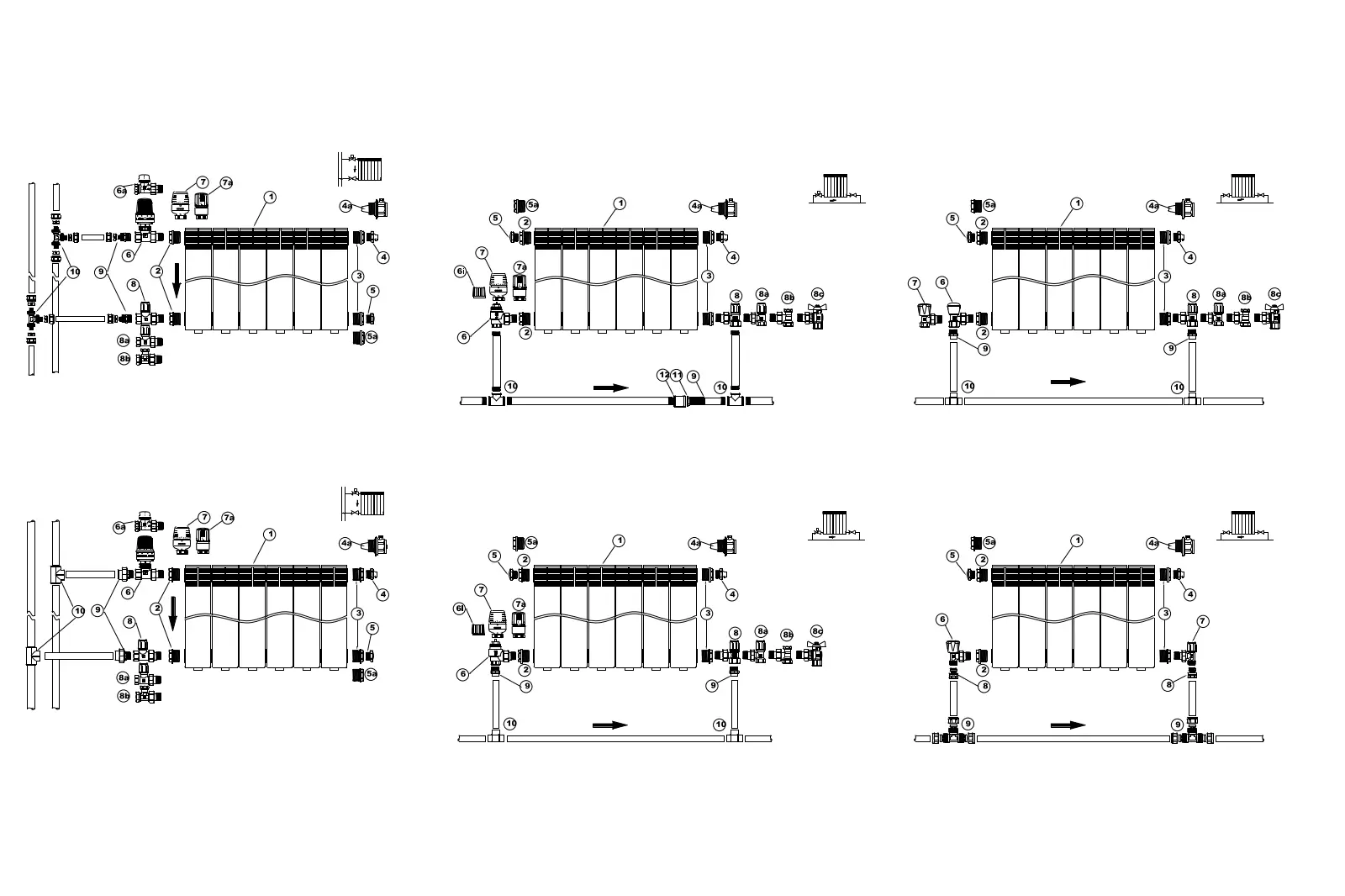
Technical AutoCAD DWG drawing detailing six standard radiator pipework connection configurations for MEP design and installation. This technical CAD resource provides a series of six distinct radiator connection schematics, outlining the necessary pipework, valves, and fitting assemblies. Each diagram illustrates a different configuration for sectional radiators, complete with numbered components denoting specific installation parts. The linework is clean, precise, and intended for integration into MEP construction documentation or tender packages. These schematics cover various supply and return orientations, ensuring clear guidance for contractors regarding valve placement, coupling types, and flow directions. The collection provides the essential technical infrastructure required for accurate mechanical system planning in residential or commercial heating projects.
The download is a 850 KB file containing an AutoCAD drawing (.dwg) drawn in all views. It opens in AutoCAD, BricsCAD, DraftSight and other DWG-compatible CAD programs, ready to insert as blocks into plans and elevations.
Professionals can insert this DWG file directly into an AutoCAD project as a reference or block. The geometry is fully editable, allowing users to adjust linework, modify valve symbols, or update leader text to align with specific project standards or local building codes. It serves as a foundational template for creating detailed mechanical plans, reducing the time required to draft standard radiator connection assemblies from scratch during the design development or construction documentation phases.