Loading page…
CAD Drawing
Motor Grader Caterpillar 140H
by Jaegeun Lim
About this asset
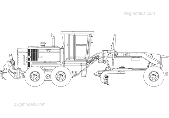
This 2D AutoCAD DWG drawing provides a precise side elevation of the Caterpillar 140H motor grader for construction site planning. The drawing represents a Caterpillar 140H motor grader in clear, two-dimensional line work. It captures the essential silhouette and mechanical components of the heavy machinery, including the rear engine housing, central operator cabin, and the articulated main frame. The blade assembly, hydraulic lift cylinders, and multi-wheel configuration are accurately depicted, showing the functional geometry of the vehicle. All lines are clean and well-defined, suitable for integration into technical site plans or elevation drawings. The file provides a high-fidelity representation of the grader's profile, facilitating clear communication of site equipment scale and layout within architectural or engineering projects.
The download is a 512 KB file containing an AutoCAD drawing (.dwg) drawn in elevation. It opens in AutoCAD, BricsCAD, DraftSight and other DWG-compatible CAD programs, ready to insert as blocks into plans and elevations.
Professional users can insert this DWG file directly into AutoCAD or compatible CAD software as a block. It is designed to be placed within site plans, sections, or elevation drawings to indicate the presence and scale of heavy machinery. The geometry is clean, allowing for easy layering, scaling, or modification to suit specific project requirements. It serves as a static visual reference, ensuring accurate representation of equipment footprints during the planning and documentation phases of construction or civil engineering projects.