Loading page…
CAD Drawing
Freight Train Carriage Components Technical Drawings
by Brandon Kintzer
About this asset
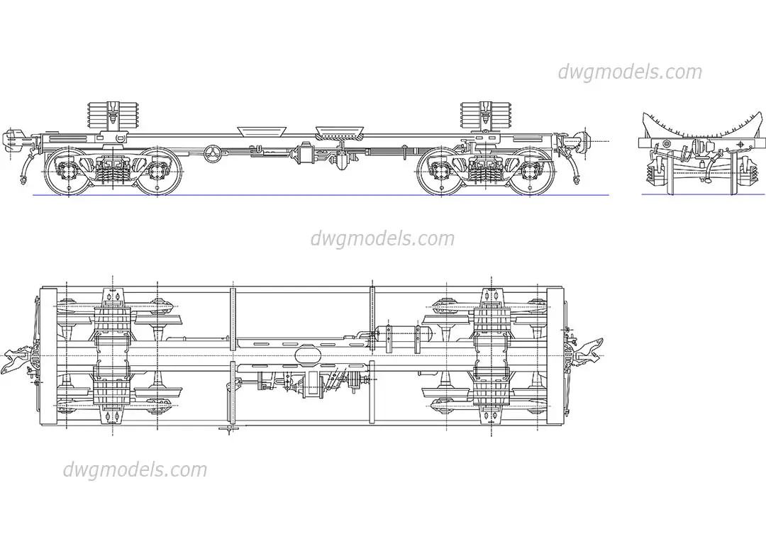
This AutoCAD DWG drawing provides detailed technical elevations and plan views of heavy-duty freight train carriage components. This technical CAD file presents a comprehensive orthographic representation of a freight train chassis and its associated mechanical assemblies. The drawing includes a side elevation, a top-down plan view, and a section-like end elevation, detailing the bogies, wheel sets, suspension elements, braking systems, and coupling mechanisms. The geometry is clean and precise, focusing on the structural framing and the articulation points necessary for rail transport. The linework is organised to show the complex interplay between the main carriage beam and the heavy-duty undercarriage components, offering a clear view of the industrial engineering involved in rail logistics.
The download is a 236 KB file containing an AutoCAD drawing (.dwg) drawn in all views. It opens in AutoCAD, BricsCAD, DraftSight and other DWG-compatible CAD programs, ready to insert as blocks into plans and elevations.
Users can insert this DWG file as a block directly into larger infrastructure or site master plans. The geometry is fully editable, allowing for customisation of individual components or scaling for specific project requirements. It is best managed by placing the drawing on a dedicated layer for transport assets. In AutoCAD, the lines are set to standard weights, ensuring clarity when plotted at various scales for technical documentation or site context development in larger civil engineering sets.