Loading page…
CAD Drawing
Industrial Grain Dryer Tower Technical CAD Drawing
by peter matthews, NCARB, LEED AP
About this asset
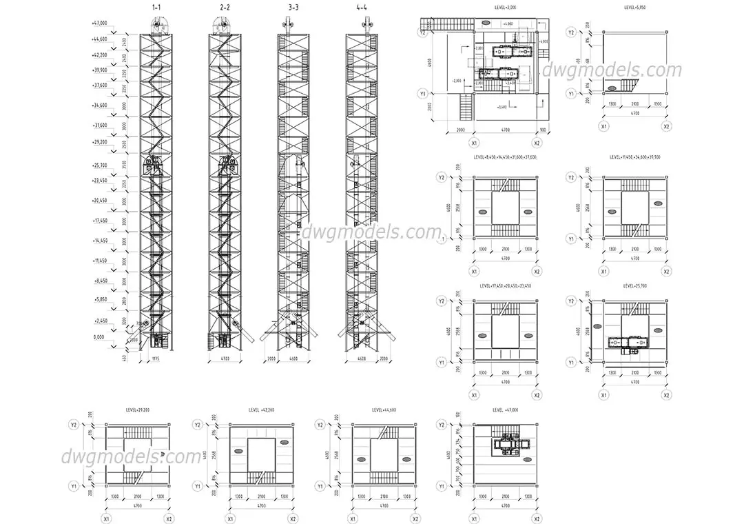
This industrial grain dryer tower CAD drawing provides detailed elevation and plan views of a steel processing structure. The drawing illustrates a multi-level industrial grain dryer tower, featuring a structural steel frame with integrated access stairs and platforms. The documentation includes four distinct vertical elevation cuts, labeled 1-1 through 4-4, detailing the tower's height and internal configuration. Accompanying these are a series of plan views representing various levels of the structure, from ground level up to the top of the tower. These plans display the footprint, primary structural grid dimensions, and the placement of internal machinery components. The line-work is clean and precise, suitable for integration into larger industrial facility layouts.
The download is a 1.9 MB file containing an AutoCAD drawing (.dwg) drawn in all views. It opens in AutoCAD, BricsCAD, DraftSight and other DWG-compatible CAD programs, ready to insert as blocks into plans and elevations.
Engineers can insert this DWG file directly into AutoCAD projects as a block or reference file. The geometry is fully editable, allowing for adjustments to the structural grid or integration into existing site plans. Users should verify the units upon insertion to ensure compatibility with the project coordinate system. Layers are typically structured to separate the structural steel elements from the dimensioning and annotation, facilitating easy toggling for cleaner presentation in final construction documentation sets.