Loading page…
CAD Drawing
Metro Carriage Technical Drawing Set
by Lara Copaescu
About this asset
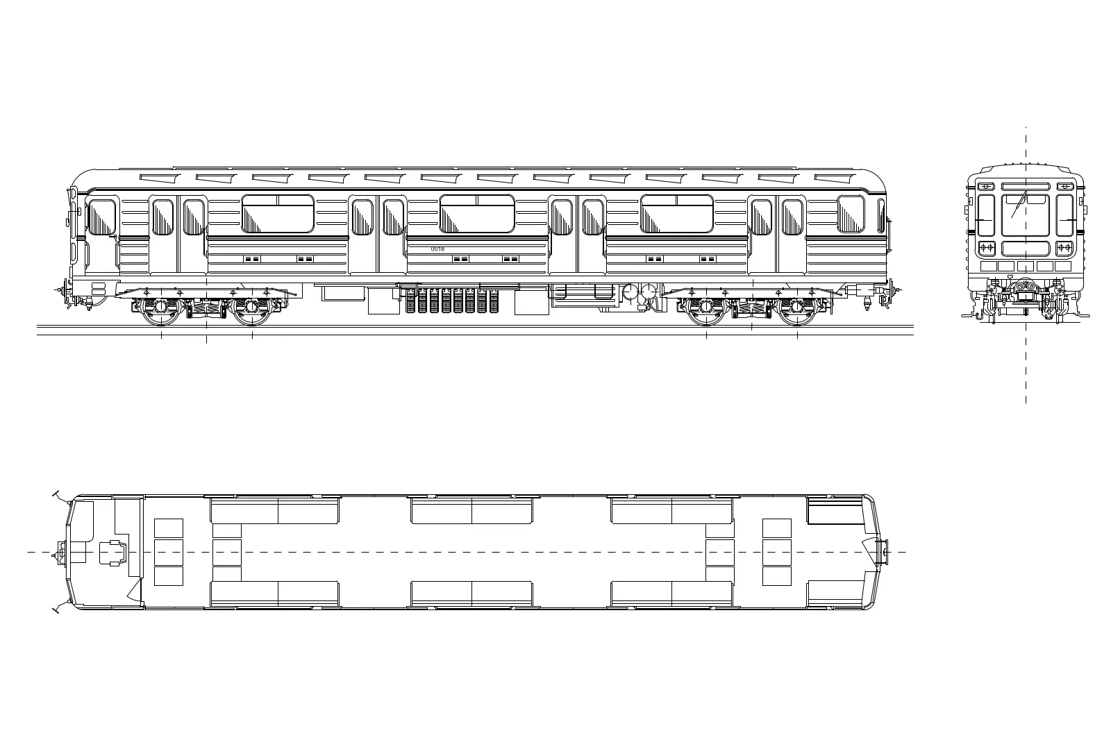
Detailed technical drawing of a metro carriage, provided as a CAD file featuring accurate side, front, and plan view projections. This technical document illustrates a standard metro carriage in high-fidelity line work. The set includes a comprehensive side elevation showing the exterior profile, door placement, and undercarriage equipment. A front elevation provides the necessary detail for the cab end, while a plan view outlines the internal layout, indicating seating arrangements and passenger circulation space. The geometry is clean and precise, suitable for architectural site plans, urban design schemes, or transit infrastructure projects. Every line is clearly defined, allowing for easy integration into larger master planning or public transport design documentation workflows.
The download is a 266 KB file containing an AutoCAD drawing (.dwg) drawn in all views. It opens in AutoCAD, BricsCAD, DraftSight and other DWG-compatible CAD programs, ready to insert as blocks into plans and elevations.
Professional users can insert this file directly into an AutoCAD project or reference it as an external block. The geometry is clean and logically organised, making it straightforward to scale for specific site conditions or to adjust line weights for presentation drawings. Because the file is saved as vector lines, it is highly efficient for use in large-scale urban masterplans where multiple carriage types or train sets need to be represented without adding significant weight to the drawing file.