Loading page…
CAD Drawing
Mercedes-Benz SK 94 Truck Chassis Drawing
by Santiago Rivera
About this asset
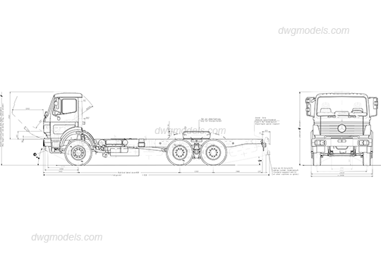
This technical AutoCAD DWG drawing provides precise side and front elevation views of a Mercedes-Benz SK 94 commercial truck chassis. The drawing illustrates the technical specifications of a Mercedes-Benz SK 94 heavy-duty truck chassis, presented in clean line art suitable for CAD environments. It includes essential dimensional data, showing the wheelbase, overall length, cabin profile, and axle placement. The front elevation highlights the iconic grille and cabin structure, while the side elevation details the exposed chassis frame, fuel tank positioning, and wheel alignment. The geometry is clean, consisting of standard CAD lines and arcs, ensuring compatibility with most drafting workflows when scaling or integrating into larger site plans or vehicle circulation diagrams.
The download is a 829 KB file containing an AutoCAD drawing (.dwg) drawn in plan and elevation. It opens in AutoCAD, BricsCAD, DraftSight and other DWG-compatible CAD programs, ready to insert as blocks into plans and elevations.
Users can insert this DWG file directly into an AutoCAD project or reference it via the XREF manager to maintain file integrity. The geometry is organised for easy manipulation, allowing for scaling or cropping to suit specific site plan requirements. Professionals typically use these CAD blocks to verify turning radii, loading bay clearances, and overall vehicle spatial requirements within logistics or industrial site designs. It is lightweight, ensuring minimal impact on file performance when working in complex master planning environments.