Loading page…
Revit Family
Pneumatic Tube Station
by Hongyang Lin
About this asset
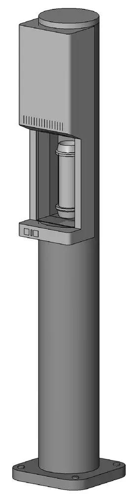
This floor-mounted pneumatic tube station Revit family provides a precise technical model for internal logistics and transport systems. The station features a robust, floor-mounted vertical column design, finished in a neutral grey industrial aesthetic. The primary housing includes a recessed loading aperture with an integrated control interface at the base of the access point. A cylindrical carrier capsule is visible within the central chamber, reflecting standard pneumatic dispatch configurations. The assembly terminates at the floor with a reinforced square mounting plate featuring four bolt holes for secure installation. Its clean, geometric form prioritises functional clarity, suitable for detailed technical documentation where mechanical infrastructure visibility is required for spatial coordination and clearance verification.
The download is a 266 KB file containing a Revit family (.rfa). Load it into a project from the Insert tab with Load Family, then place it like any other component of its category; it schedules and tags with the rest of your model.
Users should load this RFA file directly into the project environment or mechanical template. As a floor-hosted component, it snaps to floor levels, allowing for accurate positioning within corridors, service rooms, or clinical areas. The model is designed for placement within MEP workflows, providing a clear visual representation of the station footprint. Designers can utilise standard Revit alignment and dimensioning tools to coordinate the station with surrounding walls, partitions, and building services, ensuring adequate clearance for maintenance and operational access.